Imagine designing a mechanical component without knowing whether it will survive real-world loads. Manufacturing a prototype, testing it, redesigning it, and repeating the process can be expensive and time-consuming.
This is where Finite Element Analysis (FEA) becomes one of the most powerful tools in modern engineering.
FEA allows engineers to predict how a product behaves under different physical conditions before manufacturing. Whether you're designing automotive parts, aircraft components, consumer products, industrial machinery, or medical devices, FEA helps improve product reliability while reducing development costs.
In this article, you'll learn everything about Finite Element Analysis—from its basic concepts to real-world applications.
What is Finite Element Analysis (FEA)?
Finite Element Analysis (FEA) is a computer-based numerical simulation technique used to predict how a part or assembly reacts to physical forces.
Engineers use FEA to study:
- Structural strength
- Stress distribution
- Deformation
- Heat transfer
- Vibrations
- Fatigue
- Buckling
- Fluid interactions (combined with CFD)
Instead of physically testing every design, engineers simulate different conditions digitally.
Why is FEA Important?
Without simulation:
- Multiple prototypes are required
- Testing becomes expensive
- Development takes longer
- Design failures may occur after manufacturing
With FEA:
- Problems are identified early
- Better designs are created
- Development costs decrease
- Product quality improves
- Safety increases
This is why nearly every major engineering company relies on simulation before production.
The Basic Idea Behind FEA
Imagine trying to calculate stress on an extremely complicated mechanical component. The mathematics becomes impossible if you analyze the entire object at once.
Instead, FEA breaks the model into thousands (or even millions) of very small elements. These tiny elements are connected by nodes.
The software solves mathematical equations for every element individually and combines the results to predict the behavior of the complete model. This process is called Meshing.
The FEA Workflow
A typical Finite Element Analysis follows these steps.
-
Create the CAD Model
First, engineers create a 3D model using CAD software such as SOLIDWORKS, Autodesk Inventor, Fusion 360, CATIA, or Creo.
-
Assign Material Properties
The software must know the material characteristics. Common properties include Young's Modulus, Poisson's Ratio, Density, Yield Strength, and Thermal Conductivity. Different materials behave differently under identical loads.
-
Generate the Mesh
The CAD model is divided into thousands of finite elements. A finer mesh generally provides better accuracy and more detailed stress results, however, it also increases computation time.
-
Apply Boundary Conditions
Engineers define fixed supports, rollers, hinges, symmetry conditions, and contact between parts. These conditions represent how the component behaves in the real world.
-
Apply Loads
Different loads may include force, pressure, torque, gravity, temperature, acceleration, and rotational speed.
-
Solve
The software performs millions of mathematical calculations. Depending on the complexity of the model, solving may take from a few seconds to several hours.
-
Review Results
Typical outputs include Von Mises Stress, Principal Stress, Displacement, Strain, Safety Factor, Temperature Distribution, Buckling Load, and Natural Frequencies.
Types of FEA Analysis
1. Static Structural Analysis
The most commonly used simulation. Used when loads remain constant. Examples include machine brackets, frames, fixtures, and supports.
2. Thermal Analysis
Used to study heat flow. Applications include heat sinks, electronics, engines, and batteries.
3. Modal Analysis
Determines natural frequencies and vibration modes. Used extensively in automotive, aerospace, robotics, and heavy machinery industries.
4. Frequency Response Analysis
Studies vibration behavior under varying frequencies. Highly useful for rotating equipment and electric motors.
5. Buckling Analysis
Predicts structural instability under compressive loads. Common in columns, thin plates, and pressure vessels.
6. Fatigue Analysis
Estimates product life under repeated loading cycles. Essential for crankshafts, springs, aircraft structures, and suspension systems.
7. Dynamic Analysis
Used when loads change rapidly over time. Examples include crash analysis, earthquake simulation, and drop impact testing.
Understanding Von Mises Stress
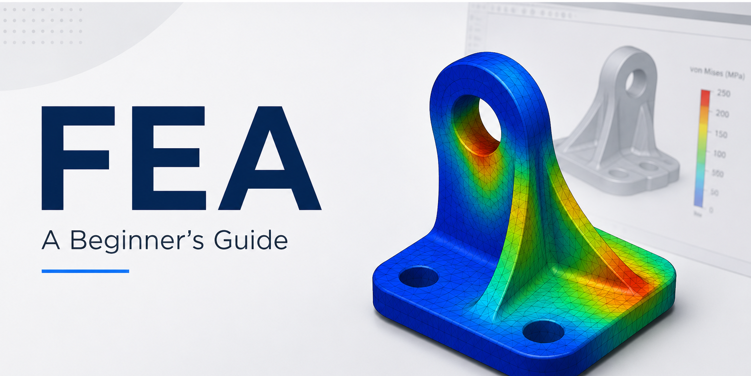
One of the most important FEA results is Von Mises Stress. It helps determine whether a ductile material will yield under loading.
- If Von Mises Stress < Yield Strength: The design is generally considered safe.
- If Von Mises Stress > Yield Strength: The component may experience permanent deformation or mechanical failure.
What is a Safety Factor?
Safety Factor indicates how much stronger a design is than required.
Example: Yield Strength = 300 MPa, Maximum Stress = 100 MPa
Safety Factor = 300 / 100 = 3
A higher safety factor generally indicates greater design reliability, though excessively high values may increase material usage, overall weight, and manufacturing cost.
Industries That Use FEA
- Automotive: Chassis design, suspension systems, engine components, and crash structures.
- Aerospace: Aircraft wings, landing gear, fuselage structures, and turbine blades.
- Manufacturing: Press tools, manufacturing fixtures, machine frames, and welded structures.
- Civil Engineering: Bridges, high-rise buildings, industrial towers, and dams.
- Medical Engineering: Bone implants, advanced prosthetics, and surgical instruments.
- Consumer Products: Mobile phones, laptops, home appliances, and sports equipment.
Advantages of FEA
- Reduces physical prototype costs
- Shortens product development time frames
- Improves final product safety
- Optimizes material usage and weight
- Detects structural design flaws early
- Enables comprehensive virtual testing
- Supports faster, iterative design variations
- Improves overall engineering confidence
Limitations of FEA
- Accuracy depends strictly on mesh quality and element choices.
- Incorrect material property inputs produce fundamentally misleading results.
- Poor or unrealistic boundary conditions will completely invalidate the simulation.
- Complex nonlinear engineering problems require advanced domain expertise.
- Simulation results should always be validated with physical experimental testing whenever possible.
Popular FEA Software
- SOLIDWORKS Simulation
- ANSYS Mechanical
- Abaqus
- Autodesk Inventor Nastran
- Siemens Simcenter
- Altair HyperWorks
- COMSOL Multiphysics
Skills Required to Learn FEA
To become highly proficient in Finite Element Analysis, you should thoroughly understand:
- Engineering Mechanics & Strength of Materials
- Machine Design Principles
- 3D CAD Modeling
- Material Science & Metallurgy
- Meshing Techniques & Convergence Criteria
- Boundary Conditions & Real-world Kinematics
- Stress Analysis & Tensor Math
Career Opportunities in FEA
FEA expertise is highly valued across modern engineering sectors. Common roles include:
- CAE Engineer (Computer-Aided Engineering)
- Simulation Specialist / Engineer
- Structural Analysis Engineer
- Mechanical Design Engineer
- Product Development Engineer
- Stress Analyst / R&D Engineer
Learn FEA with SOLIDWORKS Simulation
Understanding the theory is only the first step. Real expertise comes from building simulations, interpreting results, and validating designs through practical projects.
At CADArtifex, our SOLIDWORKS Simulation training is designed to help students, engineers, and professionals learn Finite Element Analysis through real engineering examples.
In the course, you'll learn how to:
- Set up static structural analyses.
- Create high-quality, efficient meshes.
- Apply realistic loads and boundary conditions.
- Accurately interpret stress, strain, and displacement results.
- Evaluate factor of safety and systematically optimize designs.
- Perform advanced thermal and motion studies using practical workflows.
Whether you're preparing for a design engineering role or looking to strengthen your CAE skills, hands-on simulation practice can give you a significant professional advantage.
Final Thoughts
Finite Element Analysis has transformed modern product development by enabling engineers to evaluate designs before they are manufactured. From predicting stress and deformation to optimizing performance and improving safety, FEA is an indispensable part of today's engineering workflow.
For students, learning FEA builds a strong foundation in engineering analysis. For professionals, it enhances design decision-making and opens doors to careers in simulation and product development. As industries continue to rely on virtual testing to reduce costs and accelerate innovation, mastering FEA is becoming an essential skill for every mechanical engineer.
Frequently Asked Questions (FAQs)
Is FEA difficult to learn?
Not necessarily. A basic understanding of mechanics, materials, and CAD modeling makes it much easier. With guided, practical practice, beginners can quickly master the fundamentals.
What is the difference between FEA and CFD?
FEA analyzes how solid materials respond to forces, heat, and physical deformation, while CFD (Computational Fluid Dynamics) specifically studies the behavior of fluids such as air, water, and gases.
Which industries use FEA the most?
Automotive, aerospace, defense manufacturing, civil engineering, energy, medical devices, and high-tech consumer product industries all rely heavily on FEA.
Can FEA replace physical testing?
FEA significantly reduces the need for expensive structural prototypes but does not completely replace physical testing. Safety-critical products still require final experimental validation to ensure absolute compliance and regulatory safety.
Ready to Apply FEA in Real Engineering Projects?
Understanding the theory behind Finite Element Analysis is important—but becoming job-ready requires hands-on practice with industry-standard tools.
If you want to master SOLIDWORKS Simulation and learn how to perform professional FEA studies from scratch, join the SOLIDWORKS Mastery – Live Online Training by CADArtifex. This instructor-led program covers static structural analysis, mesh generation, material assignment, loads and fixtures, stress and displacement analysis, factor of safety, Motion Study basics, and real-world engineering projects. You'll also receive live guidance, practical assignments, and a certificate upon successful completion.
What You'll Learn
- Create and prepare robust CAD models for simulation
- Generate efficient, convergent meshes for accurate results
- Apply realistic loads, fixtures, and boundary conditions
- Analyze stress, strain, displacement, and factor of safety
- Perform basic Motion Studies alongside SOLIDWORKS Simulation workflows
- Build a compelling portfolio through real engineering design projects
SOLIDWORKS Mastery – Live Online Training