
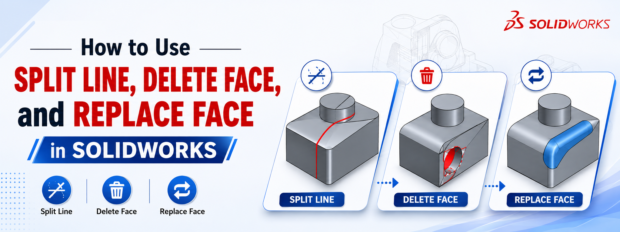
When working on more advanced SOLIDWORKS models, basic sketching and feature tools are often not enough. Mechanical designers frequently need to modify existing geometry, divide faces, remove unwanted features, or replace one surface with another without rebuilding the entire model.
Three particularly useful tools for this type of work are Split Line, Delete Face, and Replace Face.
These tools can help you edit complex models more efficiently while preserving design intent and reducing the need to start over. They are especially valuable when working with imported models, cast and machined components, molds, housings, brackets, and other mechanical parts.
✂️ Split Line
Divides an existing face into multiple regions using a sketch, curve, or plane without necessarily removing material.
🗑️ Delete Face
Removes selected faces from a solid or surface body, with smart options to patch or fill the resulting gaps.
🔄 Replace Face
Substitutes one or more existing faces with another target surface or plane, updating adjacent geometry automatically.
🔧 1. How to Use Split Line in SOLIDWORKS
Split Line is one of the most useful tools when you need to divide a face without completely changing the overall shape of a part.
💡 2. Why Use Split Line?
Split Line becomes particularly powerful when combined with other SOLIDWORKS features. After splitting a face, you can:
- Apply different appearances or textures to specific areas.
- Create localized draft or custom parting lines for mold design.
- Apply localized surface treatments or control finite element simulation (FEA) regions.
- Define explicit areas for manufacturing operations.
Practical Example: Imagine designing a plastic enclosure and wanting a textured grip around only the top portion. Instead of altering the main geometry, create a boundary sketch, run a Split Line, and apply the texture appearance to just that isolated region.
🗑️ 3. How to Use Delete Face in SOLIDWORKS
Delete Face is extremely useful when you need to remove unwanted geometry, especially when working with non-native, imported CAD files (like STEP or IGES).
Navigate to Insert ➜ Face ➜ Delete, select your target faces, and choose one of the three core modes:
- Delete and Patch: Removes the face and automatically extends surrounding geometry to close the gap. Ideal for removing holes, bosses, or fillets.
- Delete and Fill: Removes the face and generates a new surface patch to fill the gap seamlessly. Great for complex, organic, or imported geometry.
- Delete: Simply removes the face without closing the gap, turning a solid body into an open surface body.
🔍 4. Practical Delete Face Example
Suppose you receive a STEP model of a mounting bracket with an unwanted hole. Because there is no feature tree to edit:
- Select the cylindrical interior face of the hole.
- Open Delete Face.
- Select Delete and Patch.
- Click OK ✅. SOLIDWORKS heals the solid body as if the hole never existed.
👉 5. How to Use Replace Face in SOLIDWORKS
Replace Face alters the shape of an existing face by mapping it to a target surface body while keeping surrounding geometry connected.
⚖️ 6. Delete Face vs Replace Face
| Feature | Main Purpose | Typical Application |
|---|---|---|
| ✂️ Split Line | Divides an existing face | Creating isolated regions, parting lines, localized decals/draft. |
| 🗑️ Delete Face | Removes a face completely | Removing holes, fillets, bosses, or cleaning imported CAD. |
| 🔄 Replace Face | Substitutes a face with another surface | Modifying organic curvatures or matching complex contoured cuts. |
Quick Memory Rule: Split Line = Divide | Delete Face = Remove | Replace Face = Substitute
🔁 7. Using the Three Tools Together
Combining these tools provides immense power when redesigning parts without full rebuilds:
⚠️ 8. Common Problems and Troubleshooting
❌ Split Line Does Not Work
Cause: Sketch doesn't fully project across the geometry, incorrect projection vector, or invalid sketch entities.
Solution: Verify that the sketch fully covers the width of the target face and check the projection direction arrow in the PropertyManager.
❌ Delete Face Fails
Cause: Surrounding geometry cannot mathematically extend to heal the gap (common with complex fillet intersections).
Solution: Delete fillets or surrounding complex faces first, or switch from Delete and Patch to Delete and Fill.
❌ Replace Face Does Not Rebuild
Cause: The replacement surface does not fully intersect or span across the bounding edges of the solid part.
Solution: Use the Extend Surface tool to enlarge your replacement surface so it completely crosses all adjacent solid edges.
⭐ 9. Best Practices for Robust Modeling
- Keep Geometry Clean: Eliminate sliver faces, micro-edges, and gaps on imported models before attempting edits.
- Work Incrementally: Apply face operations in smaller, individual features rather than grouping dozens into one tool call.
- Check Downstream Dependencies: Ensure child features do not lose parent reference edges when a face is deleted or replaced.
🚀 Master Advanced SOLIDWORKS Workflows
Ready to move beyond basic modeling? Learn practical mechanical design, complex surfacing, assemblies, and sheet metal through real-world industry projects.
Explore CADArtifex Courses ➜
 - 7074-360x220.png)
 - 3896-360x220.png)
