
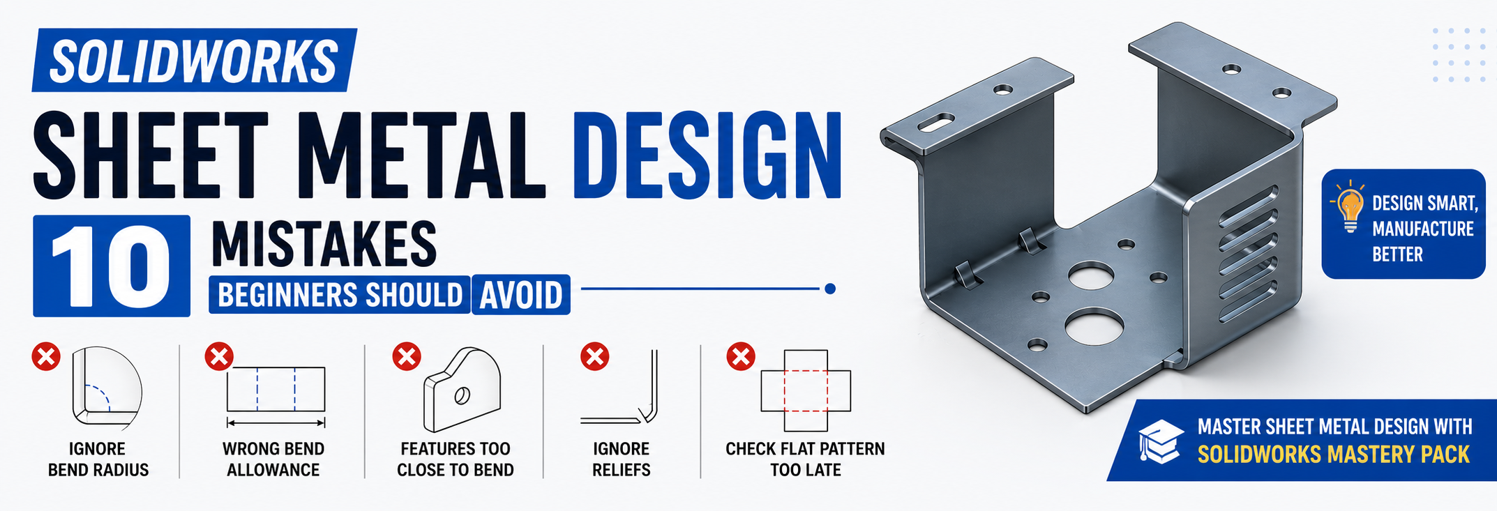
Sheet metal design looks simple at first—create a sketch, add a flange, bend the material, and generate a flat pattern. But in professional manufacturing, small modeling mistakes can lead to incorrect bend allowances, impossible features, poor flat patterns, and expensive fabrication problems.
Whether you're a mechanical engineering student, CAD beginner, or aspiring design engineer, understanding design intent and manufacturing requirements is essential when working with sheet metal in SOLIDWORKS.
In this guide, we'll cover 10 common SOLIDWORKS Sheet Metal mistakes beginners should avoid, along with practical ways to improve your workflow.
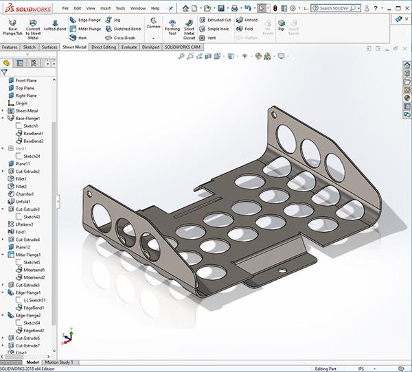
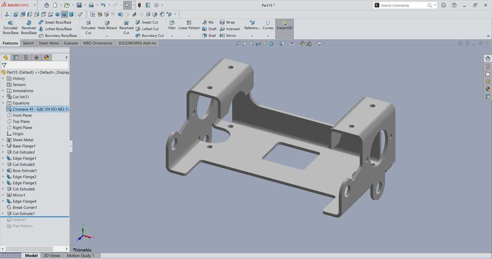
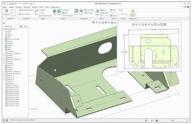
1. Using the Wrong Sheet Metal Thickness
One of the most common beginner mistakes is creating geometry without properly defining the material thickness.
For example, imagine designing a bracket that is supposed to be manufactured from 2 mm sheet metal, but the model effectively uses a different thickness.
This can affect:
- Bend geometry
- Flat pattern dimensions
- Bend allowance
- Corner conditions
- Manufacturing cost
- Overall part strength
How to avoid it
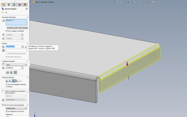
Define the correct thickness at the beginning of the design. When using Base Flange/Tab, specify the intended sheet thickness and make sure the value matches the actual manufacturing material.
2. Ignoring Bend Radius
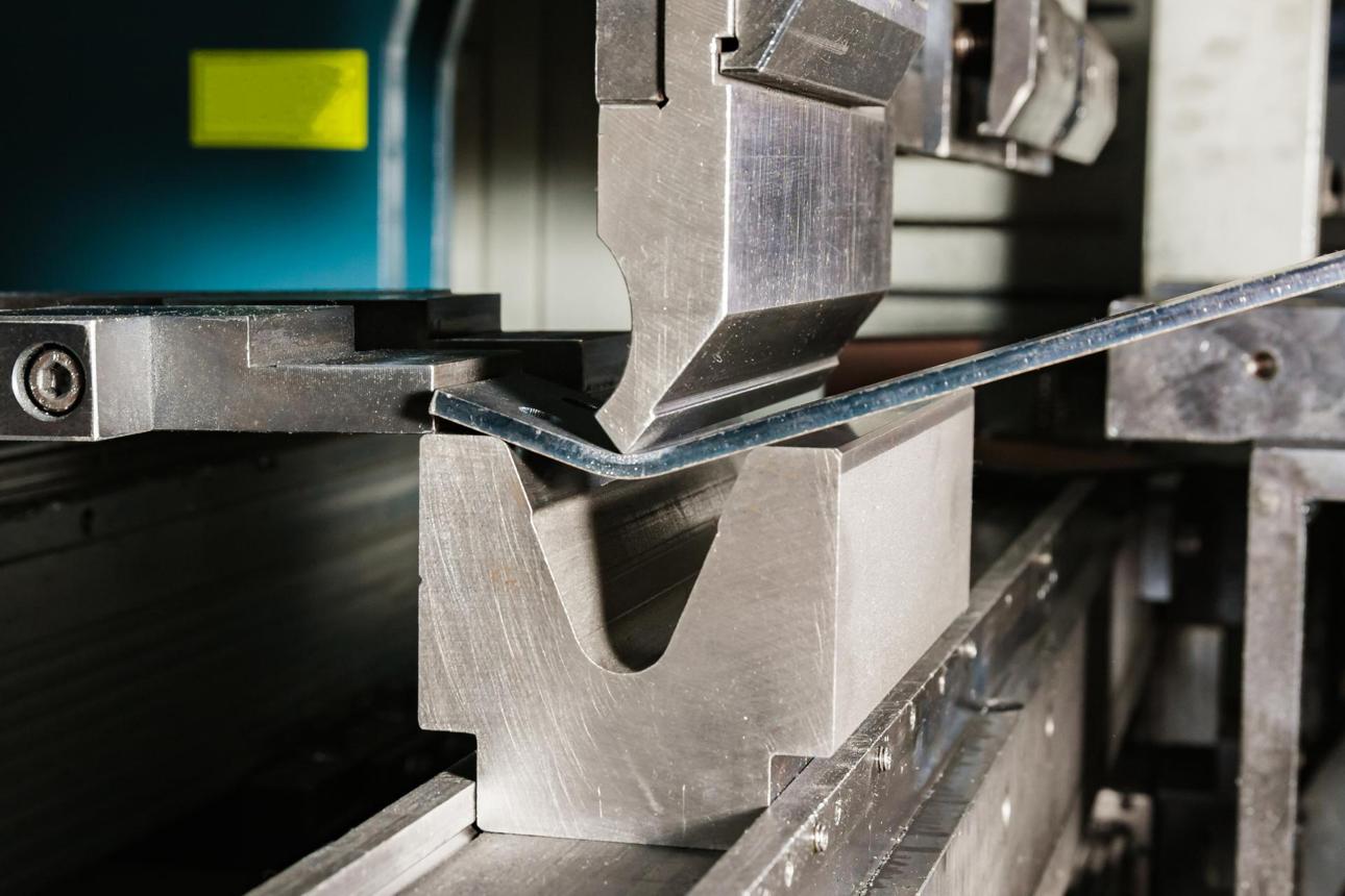
Another common mistake is choosing a bend radius without considering the material and manufacturing process.
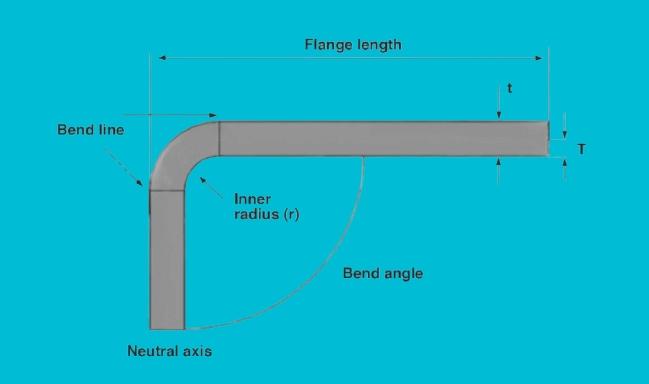
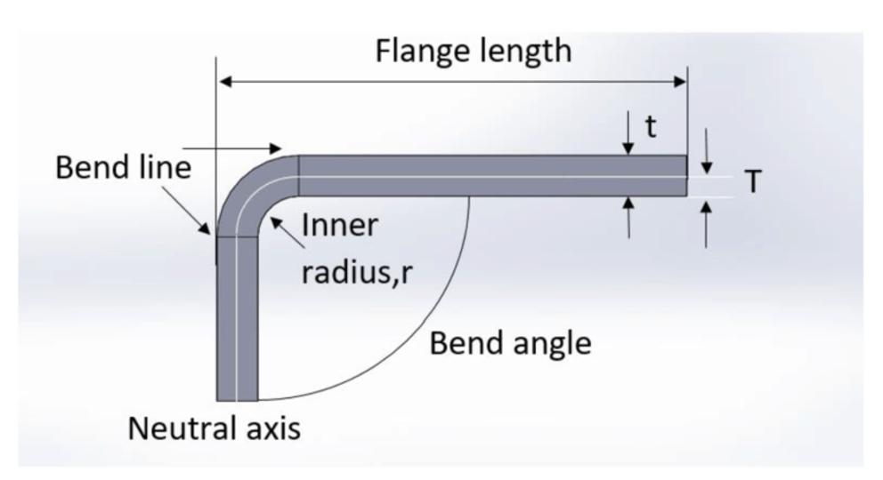
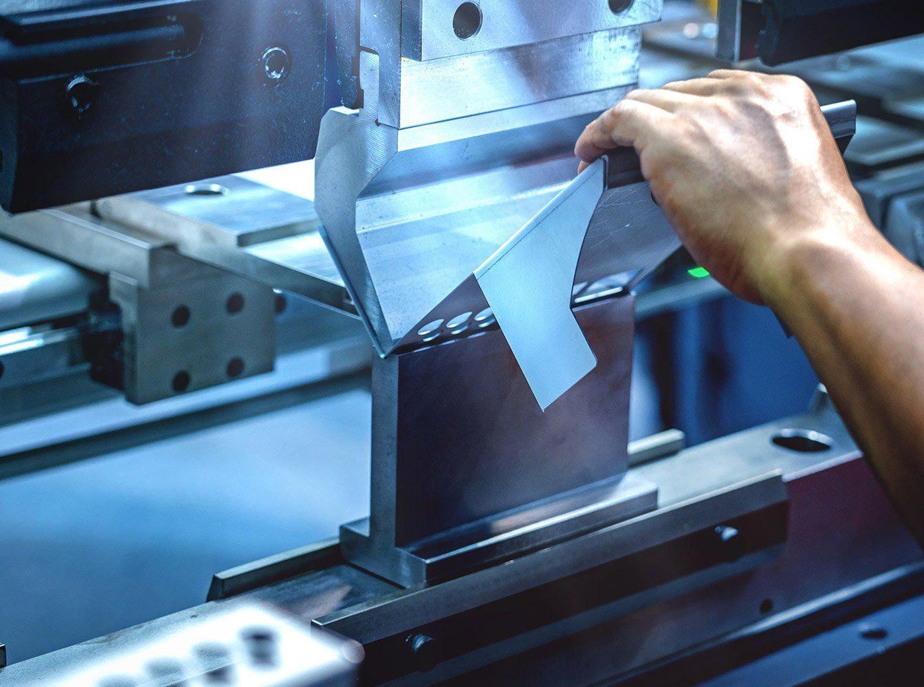
A bend radius that works for one material may not be suitable for another. The required radius depends on material type, thickness, bending process, tooling, grain direction, strength requirements, and manufacturing equipment.
Why this matters
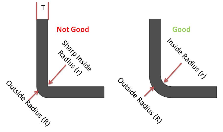
An unnecessarily small bend radius can cause:
- Cracking
- Deformation
- Tooling problems
- Manufacturing difficulties
How to avoid it
Use a realistic inside bend radius based on the material and manufacturing process. Don't simply use a very small radius because SOLIDWORKS allows you to create it.
3. Forgetting About Bend Allowance
This is one of the most important concepts in sheet metal design. When a sheet is bent, the material doesn't simply fold around a sharp corner. The material undergoes deformation, which changes the developed length of the part.
This is why the flat pattern isn't simply the sum of all the finished dimensions.
SOLIDWORKS uses parameters such as Bend Allowance, Bend Deduction, K-Factor, and Bend Tables to calculate the developed shape.
K-Factor
The K-factor represents the position of the neutral axis within the material thickness during bending.
Where:
- K = K-factor
- Thickness = sheet thickness
- Bend Radius = inside bend radius
- Bend Angle = bend angle in radians
4. Designing Features Too Close to a Bend
Beginners often place holes, slots, notches, or cutouts very close to a bend. During manufacturing, bending can distort features located too close to the bend line.
Possible problems include:
- Hole deformation
- Distorted edges
- Reduced accuracy
- Tool interference
- Difficulty during fabrication
How to avoid it
Maintain an appropriate distance between features and bend regions. The required distance depends on material thickness, bend radius, material, tooling, and manufacturing process.
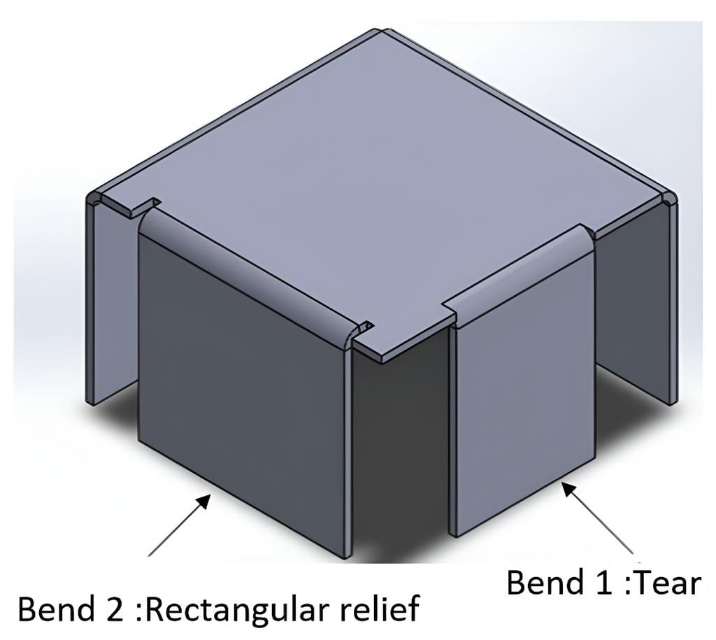
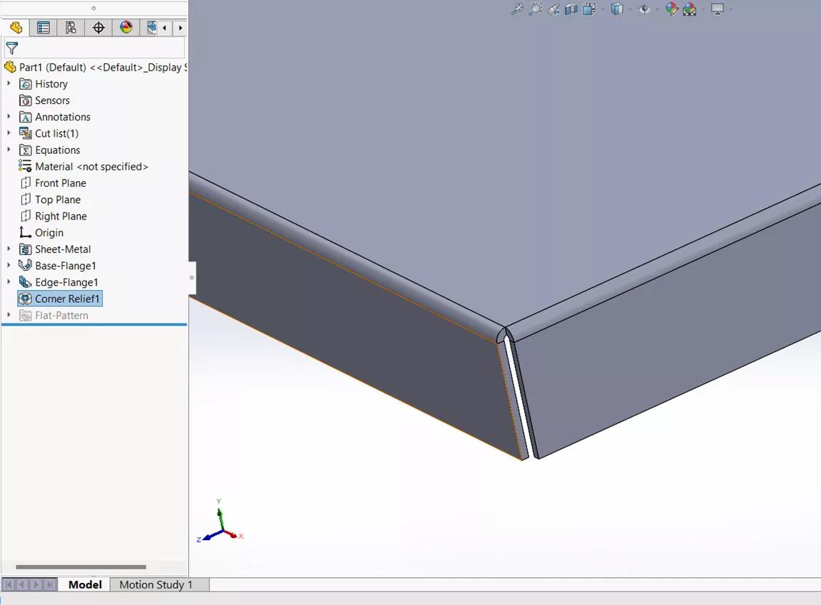
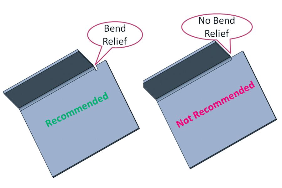
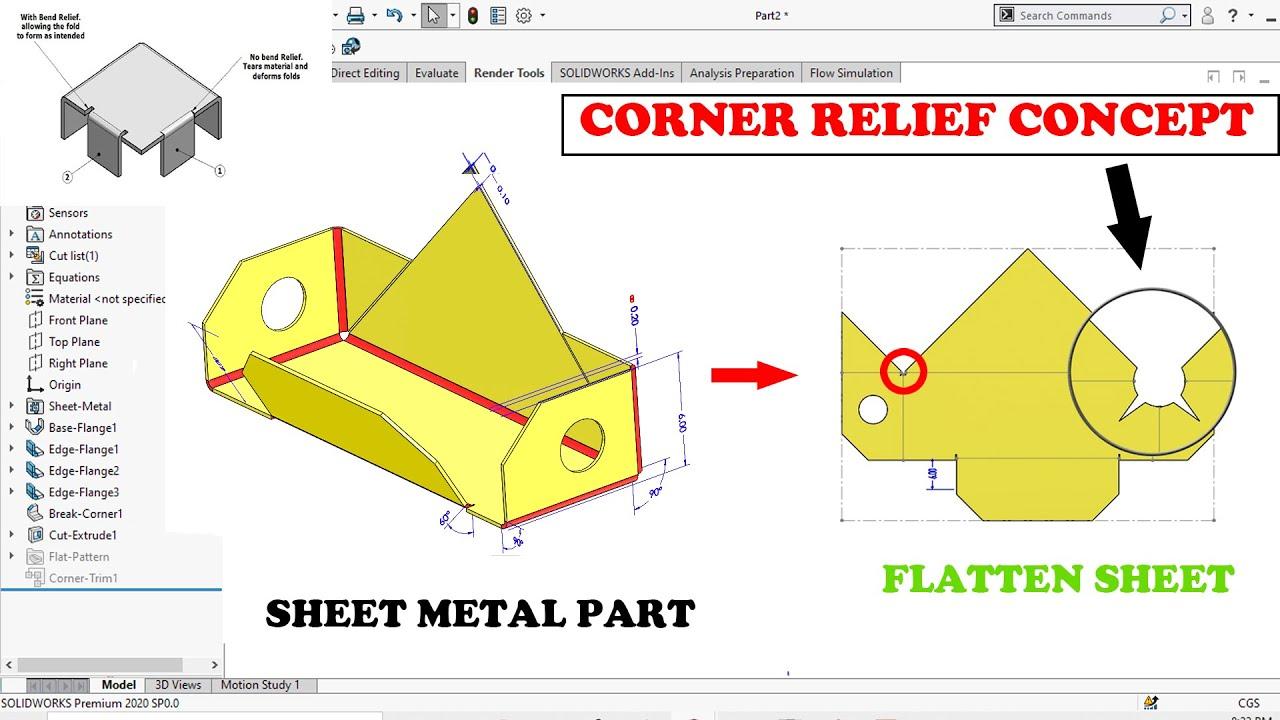
5. Ignoring Reliefs
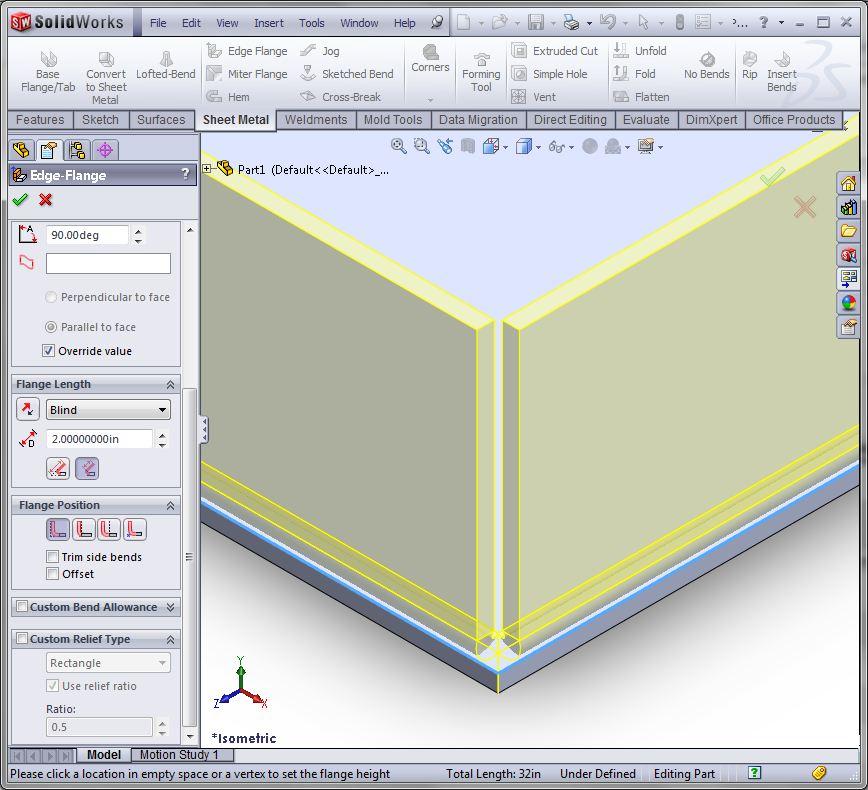
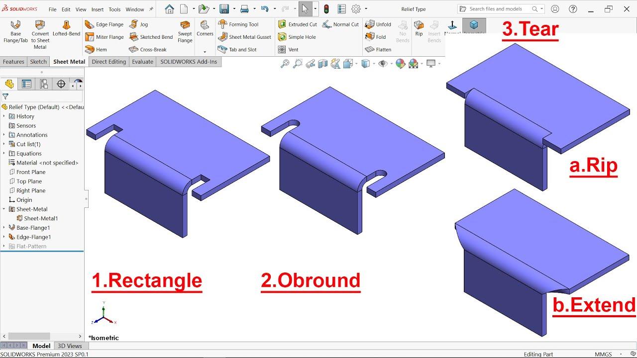
Sheet metal parts often require reliefs at corners and bends. Without appropriate relief geometry, the material may overlap or deform during bending.
Common types include:
- Bend relief
- Corner relief
- Tear relief
Reliefs can help prevent:
- Material tearing
- Unwanted deformation
- Overlapping material
- Difficult bending operations
SOLIDWORKS provides tools that help create and manage these conditions. Consider manufacturing requirements while creating the initial geometry rather than waiting until the end of the model.
6. Using Too Many Unnecessary Features
Another common beginner mistake is creating complicated feature trees for relatively simple sheet metal components.
A complicated feature tree can make the model difficult to edit, slower to rebuild, harder for another designer to understand, and more prone to errors.
Better approach
Use SOLIDWORKS' dedicated sheet metal features whenever possible, such as:
- Base Flange
- Edge Flange
- Hem
- Jog
- Sketched Bend
- Closed Corner
- Unfold
- Fold
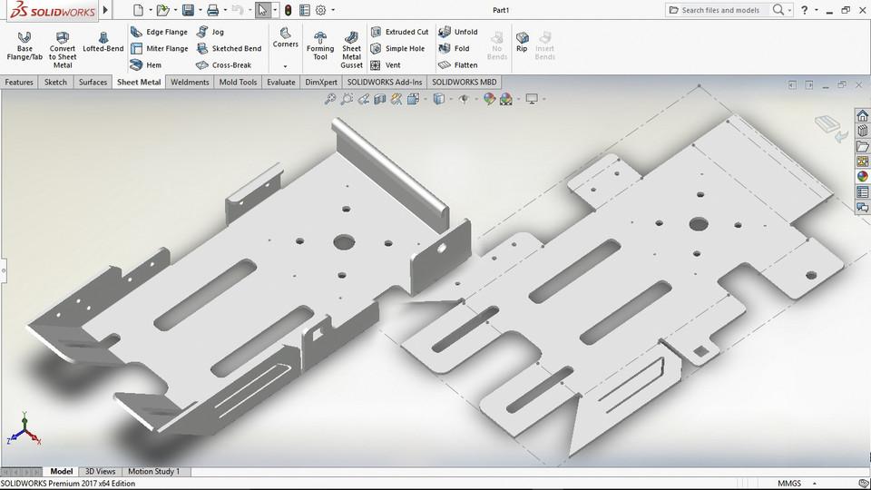
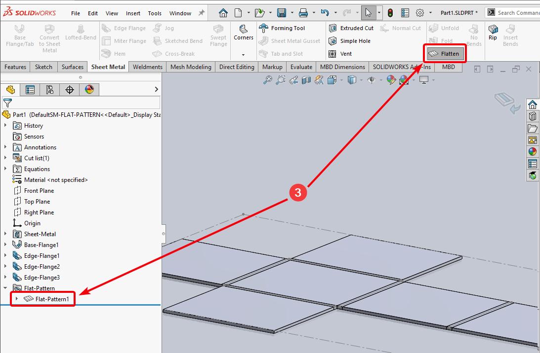
7. Creating the Flat Pattern Too Late
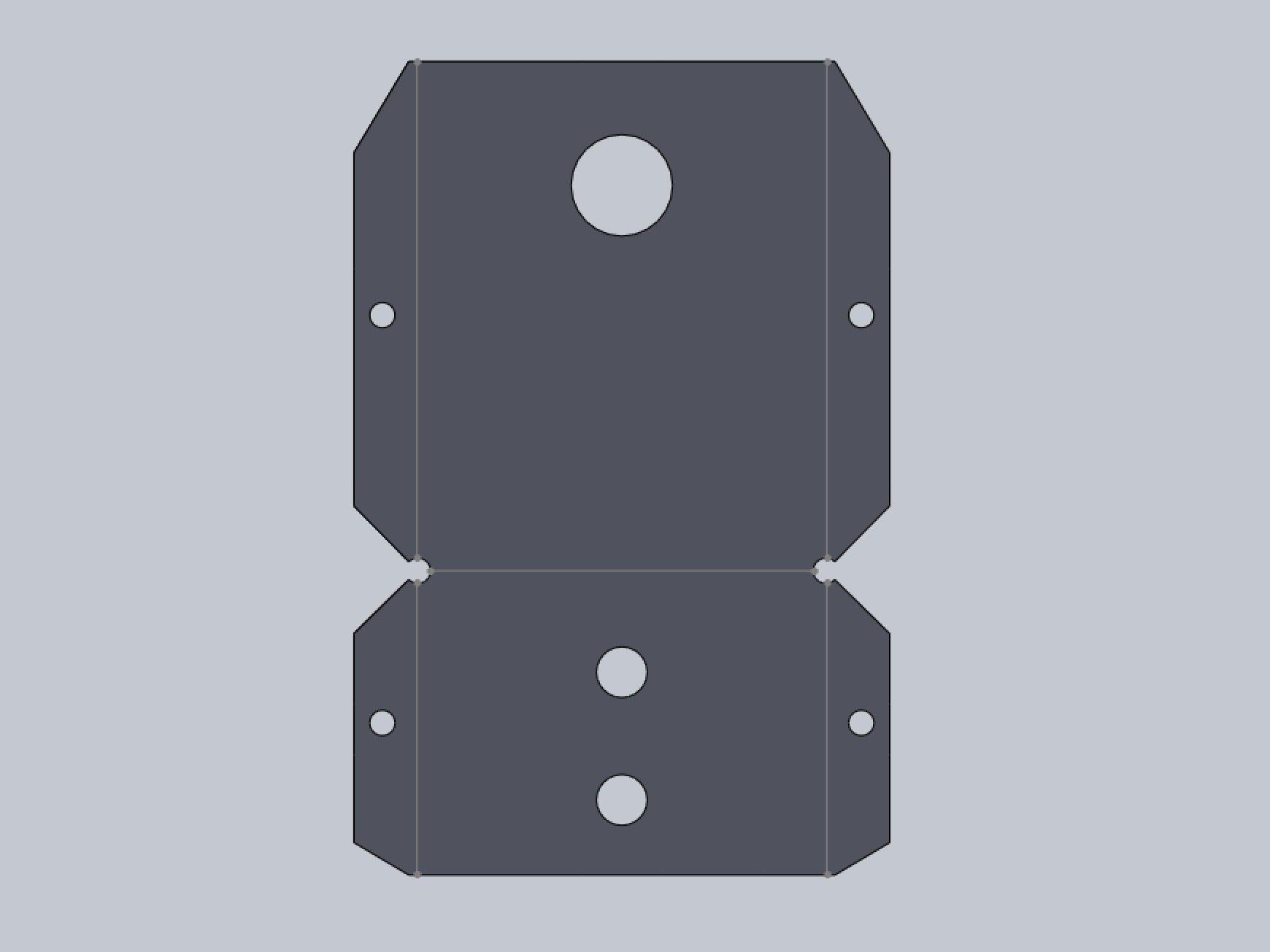
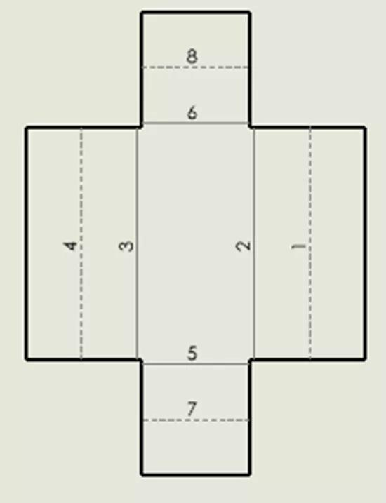
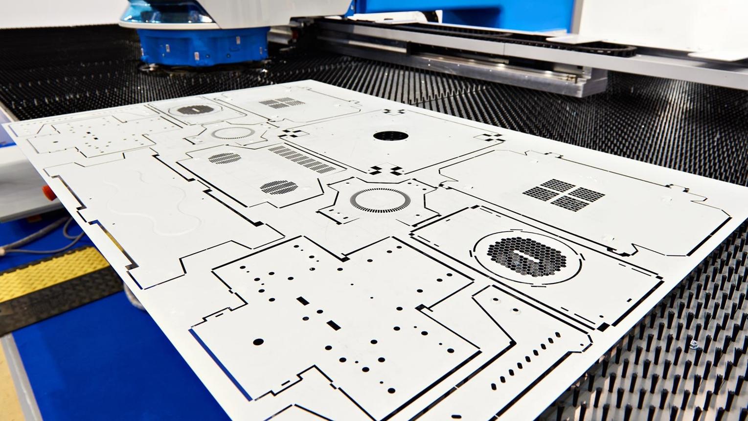
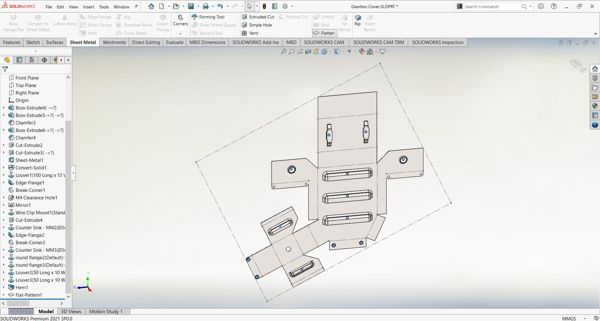
The flat pattern isn't just a final drawing output. It is one of the most important checks for a sheet metal model.
A folded model may look perfect in 3D but still produce a problematic flat pattern.
Look for:
- Unexpected overlaps
- Incorrect bend directions
- Missing reliefs
- Strange corner geometry
- Incorrect bend lines
- Unwanted gaps
- Manufacturing problems
8. Ignoring Bend Direction and Bend Notes
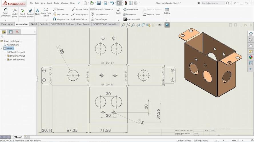
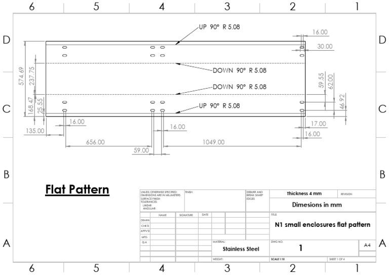
A flat pattern must communicate useful manufacturing information. The manufacturer needs to know where to bend, which direction to bend, the bend angle, bend radius, material, and thickness.
SOLIDWORKS can generate bend lines and related information in drawings.
Common mistake
Beginners may create a beautiful 3D model but fail to provide enough information for manufacturing.
Better workflow
3D Model ? Flat Pattern ? Drawing ? Bend Information ? Manufacturing
Make sure the drawing communicates the required fabrication information clearly.
9. Using Sharp Corners Everywhere
Real-world sheet metal parts generally don't behave like idealized CAD geometry. Sharp corners can create manufacturing and safety problems.
An exposed sharp edge can:
- Be difficult to manufacture
- Increase injury risk
- Create stress concentrations
- Affect finishing operations
- Produce an undesirable appearance
Better approach
Consider appropriate:
- Edge breaks
- Fillets
- Corner treatments
- Hem features
10. Designing Without Considering Manufacturing
This is perhaps the biggest mistake of all. A model can be geometrically correct but impossible or expensive to manufacture.
This is why Design for Manufacturing (DFM) should be considered throughout the design process.
Material
- Is the material available?
- Is the thickness correct?
Bending
- Can the required bend radius be achieved?
- Is there enough clearance for the tooling?
Cutting
- Can the holes and slots be cut efficiently?
- Are the features large enough to manufacture?
Forming
- Are there features that require special tooling?
Assembly
- Does the part fit with neighboring components?
- Are fasteners accessible?
Flat Pattern
- Does the developed shape make sense?
- Can it actually be cut from sheet stock?
5 SOLIDWORKS Sheet Metal Best Practices
Once you avoid the common mistakes above, these practices can make your workflow even better.
1. Build With Design Intent
Don't just model the shape. Think about how the part will change in the future. Use proper dimensions, relations, references, parameters, and feature order.
2. Use Material-Specific Parameters
Don't assume that one bend radius or K-factor works for every material. Maintain standardized values for your manufacturing environment.
3. Keep Your Feature Tree Organized
Use meaningful feature names such as Base Flange, Front Flange, Mounting Hole, Bend Relief, Hem, and Final Cut.
4. Check the Flat Pattern Frequently
A reliable workflow is:
5. Think Like a Manufacturer
When designing, don't ask only:
Also ask:
That mindset separates a CAD modeler from a professional mechanical designer.
SOLIDWORKS Sheet Metal Design Workflow
A practical beginner workflow can look like this:
- Define material and thickness
- Set bend parameters
- Create Base Flange
- Add Edge Flanges
- Add bends and reliefs
- Add holes and cutouts
- Check bend clearances
- Flatten the model
- Inspect the flat pattern
- Create the manufacturing drawing
- Verify DFM requirements
- Release for manufacturing
Final Thoughts
Learning SOLIDWORKS Sheet Metal isn't just about memorizing commands. The real skill is understanding the relationship between CAD geometry, material behavior, bending, flat patterns, and manufacturing.
The 10 mistakes covered in this article are especially important for beginners:
- Using the wrong sheet thickness
- Ignoring bend radius
- Forgetting bend allowance
- Placing features too close to bends
- Ignoring reliefs
- Using unnecessary features
- Checking the flat pattern too late
- Ignoring bend direction and manufacturing notes
- Using sharp corners everywhere
- Designing without considering manufacturing
If you build the habit of checking thickness ? bend parameters ? reliefs ? feature clearances ? flat pattern ? manufacturing, your SOLIDWORKS sheet metal models will become much more reliable and production-ready.
Master SOLIDWORKS with Real-World Projects
Take your SOLIDWORKS skills beyond individual commands. Learn practical modeling, assemblies, sheet metal, mechanical design, and project-based workflows with the SOLIDWORKS Mastery Pack.
Explore SOLIDWORKS Mastery Pack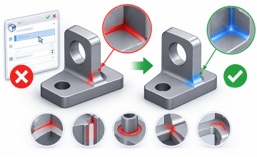
 - 7074-360x220.png)
 - 3896-360x220.png)
