In mechanical design, creating a part that looks correct in CAD is only the beginning. When two or more components must assemble, move, rotate, slide, or remain fixed together, dimensional accuracy becomes critical.
This is where tolerance and fit become essential.
A shaft may be designed as exactly 20 mm in Fusion 360, but manufacturing it at precisely 20.000 mm is rarely practical or necessary. Likewise, a hole modeled at exactly 20 mm may actually be produced slightly larger or smaller. These variations are controlled through tolerances, while the resulting relationship between mating components is described by their fit.
For Fusion 360 users, understanding tolerance and fit helps bridge the gap between 3D CAD modeling and real-world manufacturing.
What Is Tolerance in Mechanical Design?
Tolerance is the permissible variation in a dimension from its specified nominal value.
For example, suppose a shaft has a nominal diameter of: 20 mm
If its specified tolerance is: 20 ± 0.02 mm
The acceptable manufactured diameter is:
- Minimum: 19.98 mm
- Maximum: 20.02 mm
So, the shaft does not have to be exactly 20.000 mm. Any dimension within the specified limits can be acceptable.
Why Are Tolerances Necessary?
Manufacturing processes always have some degree of variation. Factors such as:
- Machine accuracy
- Tool wear
- Material properties
- Temperature
- Measurement accuracy
- Manufacturing process
- Operator variation
can affect the final dimensions. Therefore, instead of expecting perfect dimensions, engineers define an acceptable range.
Nominal, Actual, Maximum, and Minimum Dimensions
Understanding a few basic terms makes tolerance easier to understand.
1. Nominal Dimension
The nominal dimension is the target or reference dimension.
Example: 50 mm
2. Actual Dimension
The actual dimension is what is measured on the manufactured component.
Example: 49.97 mm
3. Upper Limit
The largest acceptable dimension.
Example: 50.05 mm
4. Lower Limit
The smallest acceptable dimension.
Example: 49.95 mm
The difference between the upper and lower limits represents the total tolerance:
For this example: 50.05 − 49.95 = 0.10 mm
What Is Fit?
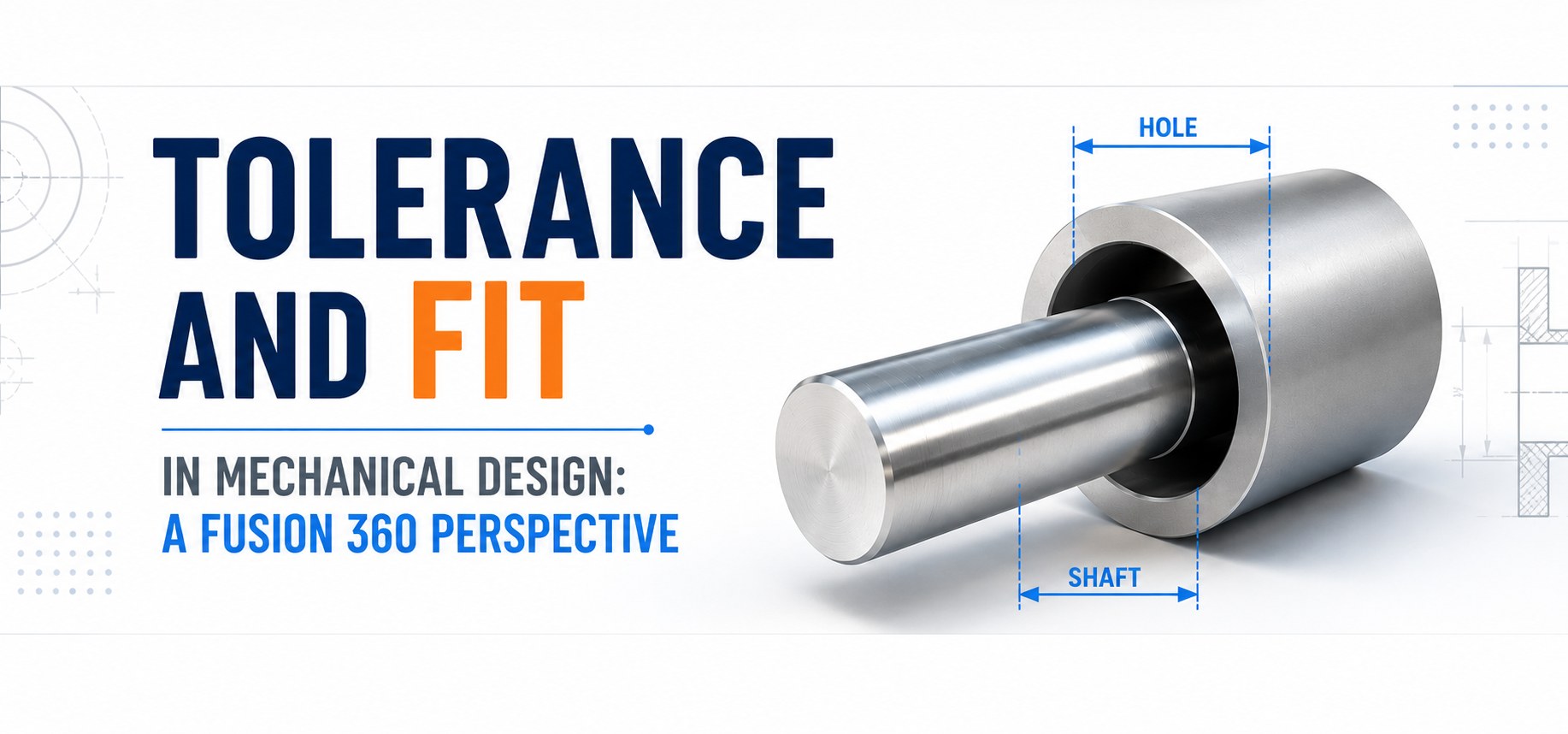
While tolerance controls the variation of individual dimensions, fit describes the relationship between two mating components. A common example is a shaft and hole.
Imagine designing a shaft that needs to fit inside a hole. Depending on their dimensions and tolerances, the resulting fit could be:
- Clearance fit
- Transition fit
- Interference fit
These three categories are fundamental to mechanical design.
1. Clearance Fit
A clearance fit means there is always some space between the mating components. The hole is larger than the shaft.
Example:
Hole: 20.05–20.10 mm
Shaft: 19.95–20.00 mm
The shaft can enter the hole without interference.
Typical Applications:
Clearance fits are commonly used when components need to:
- Rotate
- Slide
- Move freely
- Be assembled and disassembled
Examples include: Bearings and shafts, sliding mechanisms, hinges, guide pins, and bushings.
However, the amount of clearance matters. Excessive clearance can cause vibration, noise, misalignment, reduced accuracy, and wear.
2. Interference Fit
An interference fit occurs when the shaft is larger than the hole. The components cannot normally be assembled without applying force or using methods such as heating or cooling.
Example:
Hole: 19.98–20.00 mm
Shaft: 20.02–20.04 mm
The shaft must be pressed into the hole.
Typical Applications:
Interference fits can be used for permanent assemblies, gear mounting, pulley mounting, bushings, rotating components, and press-fit components. The advantage is that the components can remain securely connected without additional fasteners.
3. Transition Fit
A transition fit lies between clearance and interference fits. Depending on the actual manufactured dimensions, the assembly may have a small clearance or a small interference.
Transition fits are useful when accurate positioning is important while still allowing relatively easy assembly.
Typical applications include: Locating components, precision assemblies, alignment features, and mechanical housings.
Tolerance vs Fit
These terms are related but not identical.
| Concept | Meaning |
|---|---|
| Tolerance | Permissible variation in a dimension |
| Fit | Relationship between mating dimensions |
| Clearance | Space between mating components |
| Interference | Overlap between mating dimensions |
| Nominal Dimension | Target/reference dimension |
Think of it this way:
- Tolerance controls variation.
- Fit controls the relationship between components.
Why Tolerance Matters in Fusion 360
Fusion 360 allows designers to create highly accurate digital models. However, a CAD model does not automatically represent manufacturing capability.
For example, you might create a hole with a diameter of exactly 10.000 mm. But if the component is going to be CNC machined, 3D printed, cast, or manufactured using another process, the actual hole will have some variation.
Therefore, the designer needs to consider:
Tolerance is the bridge between these stages.
Tolerance in Fusion 360 Drawings
A useful Fusion 360 workflow is to separate nominal modeling from manufacturing documentation. The 3D model can represent the intended geometry, while the technical drawing communicates the required dimensional limits and manufacturing information.
For example, instead of simply documenting Ø20 mm, a drawing might specify Ø20 ± 0.02 mm. This tells the manufacturer that the acceptable range is 19.98–20.02 mm.
The important point is that the CAD model and drawing serve different purposes. The model communicates geometry and design intent, while the drawing can communicate manufacturing requirements, tolerances, materials, surface requirements, and other specifications.
Types of Tolerances
1. Bilateral Tolerance
Variation is allowed in both directions.
Example: 50 ± 0.05 mm
Acceptable range: 49.95–50.05 mm
2. Unilateral Tolerance
Variation is allowed primarily in one direction.
Example: 50 +0.05 / 0 mm
Acceptable range: 50.00–50.05 mm
This can be useful when a dimension must not fall below or above a specific value.
3. Limit Tolerancing
The upper and lower limits are directly specified.
Example: 49.95–50.05 mm
This immediately communicates the acceptable range.
4. General Tolerances
Instead of specifying a tolerance for every dimension, a drawing can define general tolerances that apply to dimensions unless otherwise specified. This can simplify technical drawings and manufacturing documentation.
Hole and Shaft Fits
One of the most important applications of tolerance is the hole-and-shaft system. Consider a shaft and hole both having a nominal diameter of 20 mm. If we define suitable tolerances, we can intentionally create:
- Clearance: Hole is always larger than shaft.
- Transition: Hole and shaft may produce either small clearance or small interference.
- Interference: Shaft is always larger than hole.
This relationship is often defined using standardized fit systems such as ISO limits and fits. Common designations include: H7/h6, H7/g6, and H7/p6.
The exact fit should be selected based on the function of the assembly, manufacturing method, material, operating conditions, and required accuracy.
Understanding Allowance
Allowance is the intentional difference between mating dimensions at their material-condition limits. It helps establish the intended relationship between two mating components.
For example, in a clearance-fit system, the design may intentionally provide a minimum amount of clearance so that the parts do not bind even when manufactured toward their tolerance limits.
Allowance is particularly important for sliding assemblies, rotating components, press fits, and precision locating features.
Worst-Case Tolerance Analysis
One important concept for intermediate designers is tolerance stack-up. Consider an assembly containing several dimensions:
- Dimension A = 10 ± 0.05 mm
- Dimension B = 20 ± 0.05 mm
- Dimension C = 30 ± 0.10 mm
The total nominal dimension is: 10 + 20 + 30 = 60 mm
The worst-case tolerance can be calculated by adding the individual tolerances:
±(0.05 + 0.05 + 0.10) = ±0.20 mm
Therefore, the resulting dimension could theoretically range from 59.80 mm to 60.20 mm. This is known as worst-case tolerance analysis. It is particularly important when several components contribute to a critical assembly dimension.
Tolerance Stack-Up in Fusion 360 Assemblies
Fusion 360 can help visualize the relationships between components in an assembly. A designer can:
- Create individual components.
- Define nominal dimensions.
- Position components using joints.
- Identify critical interfaces.
- Determine which dimensions affect assembly performance.
- Document required tolerances.
- Evaluate potential interference or clearance.
However, tolerance analysis should not be treated simply as a CAD operation. It is fundamentally an engineering and manufacturing problem. The designer needs to understand: Which dimensions actually affect function?
Example: Designing a Shaft and Bearing Assembly
Suppose you're designing a rotating shaft that will be installed into a bearing. You might begin with a nominal shaft diameter. However, simply modeling the shaft and bearing with identical nominal dimensions is not enough. You need to consider:
- Required fit
- Bearing specifications
- Shaft manufacturing process
- Operating temperature
- Rotational speed
- Load
- Lubrication
- Assembly method
- Required alignment
The final tolerance specification should therefore come from the functional requirements, not simply from what is convenient to model.
How Material Affects Fit
Material selection can also influence tolerance decisions. Different materials behave differently under temperature changes, loading, machining, moisture, and wear.
For example, thermal expansion can become important in precision assemblies. If two components operate at significantly different temperatures, their dimensions may change. Therefore, a fit that works perfectly at room temperature might behave differently under operating conditions.
Tolerance and Manufacturing Method
Not every manufacturing process can economically achieve the same tolerance.
| Manufacturing Process | Typical Consideration |
|---|---|
| 3D Printing | Generally larger dimensional variation |
| CNC Machining | Higher dimensional accuracy |
| Casting | Often requires machining for precision features |
| Injection Molding | Requires consideration of shrinkage |
| Sheet Metal | Bend and material variation must be considered |
The exact achievable tolerance depends on the specific process, machine, material, geometry, and supplier capability.
Tolerance vs Accuracy vs Precision
Accuracy
How close a measurement is to the intended or true value.
Precision
How consistently repeated measurements agree with each other.
Tolerance
The acceptable range specified by the designer.
For example, a dimension can have a tight tolerance but still be produced inaccurately if the manufacturing process is incorrectly controlled.
Common Tolerance Mistakes in CAD Design
- Modeling Everything With Exact Dimensions: A model may look perfect at nominal dimensions but fail during manufacturing or assembly.
- Ignoring Manufacturing Capability: A tolerance should be realistic for the manufacturing process.
- Making Every Tolerance Extremely Tight: Tighter is not always better.
- Ignoring Temperature: Thermal expansion can affect precision assemblies.
- Forgetting Tolerance Stack-Up: Several small variations can combine into a significant assembly error.
- Not Defining Critical Features: Not every dimension requires the same level of control.
- Designing Without Considering Assembly: A theoretically correct part may still be difficult or impossible to assemble.
Best Practices for Fusion 360 Designers
When working on intermediate-level mechanical designs, follow these principles:
- Start with function: Determine what the component needs to do before selecting tolerances.
- Identify critical dimensions: Focus tighter control on dimensions that affect performance.
- Consider manufacturing early: Think about how the part will actually be produced.
- Use appropriate fits: Select clearance, transition, or interference based on the application.
- Check tolerance stack-ups: Especially for multi-component assemblies.
- Avoid unnecessary precision: Use the least restrictive tolerance that still satisfies the design requirement.
- Document manufacturing requirements clearly: Use appropriate dimensions, tolerances, notes, and standards in technical drawings.
Conclusion
Tolerance and fit are fundamental concepts that connect CAD design with real-world engineering. Fusion 360 allows designers to create precise parametric models, assemblies, and manufacturing documentation, but the quality of a mechanical design depends on more than accurate geometry. Designers must understand how dimensions vary during manufacturing and how those variations affect assembly and performance.
A successful mechanical designer therefore thinks beyond “Does the model look correct?” and asks: “Will the manufactured components fit, function, and perform as intended?”
Understanding tolerances, clearance, interference, transition fits, allowance, and tolerance stack-up helps Fusion 360 users create designs that are not only visually accurate but also manufacturing-ready and functionally reliable.
Take Your Fusion 360 Skills to the Next Level
Understanding tolerance and fit is essential, but applying these concepts to real mechanical designs is where your skills truly develop. Want to go beyond theory and build real-world Fusion 360 projects?
🚀 Master Fusion 360 with CADArtifex
The Fusion 360 Mastery Pack: Design, Sculpt & Build Real Projects (6-in-1 Course Combo) combines professional video training and project-based learning to help you develop practical Fusion 360 skills.
With the Mastery Pack, you get:
- 🎥 26+ hours of on-demand video training
- 📚 6 complete learning resources
- 🧹 100+ real-world design projects & exercises
- 🎨 Surface Modeling & T-Spline Sculpting
- ⚙️ Mechanical Parts & Assemblies
- 📐 Engineering Drawings & Workflows
- 💼 Portfolio-focused project experience
- ∞ Lifetime access and future updates
Whether you're a beginner or an intermediate Fusion 360 user, the Mastery Pack helps you move from learning individual tools to designing complete, professional projects.
👉 Start Learning with the Fusion 360 Mastery Pack - 6476-360x220.png)