
Introduction
In the world of mechanical design and product development, collaborating with customers, suppliers, and manufacturing partners often means working with CAD files created in different software. One of the most common neutral file formats used for exchanging 3D models is the STEP (Standard for the Exchange of Product Data) file.
Whether you're importing models from Autodesk Inventor, Fusion 360, CATIA, Creo, Siemens NX, or Solid Edge, chances are you'll receive a STEP file instead of a native SOLIDWORKS part.
The challenge? Imported STEP models don't contain the original feature history. Instead of seeing sketches, extrudes, fillets, and patterns, you'll usually find a single Imported feature in the FeatureManager Design Tree. This makes editing seem difficult, especially for users who are accustomed to modifying parametric features.
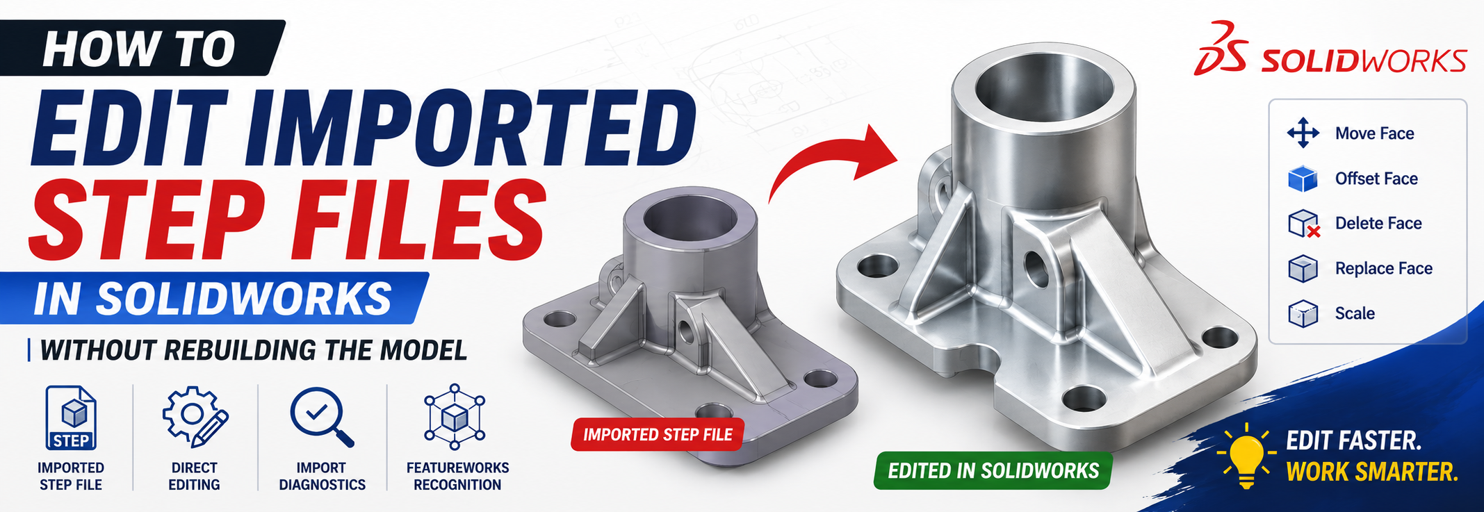
Fortunately, SOLIDWORKS provides several powerful tools that allow you to edit imported STEP files without rebuilding the entire model from scratch. Using Direct Editing tools, FeatureWorks, Import Diagnostics, and geometry repair utilities, you can quickly modify imported models while preserving design intent and saving valuable engineering time.
- Understand imported STEP geometry
- Prepare imported models for editing
- Modify imported parts using Direct Editing
- Recognize features with FeatureWorks
- Repair damaged imported geometry
- Edit holes, fillets, bosses, and pockets
- Improve workflow efficiency when working with supplier CAD data
Let's get started.
What Is a STEP File?
A STEP file is an internationally recognized neutral CAD format developed under ISO 10303. It allows engineers to exchange 3D models between different CAD systems while maintaining accurate geometry.
Unlike native SOLIDWORKS files (.SLDPRT), STEP files contain only geometric information--not the feature history used to create the model.
Common STEP file extensions include:
.STEP.STP
Because STEP files are widely supported across CAD software, they are commonly used in industries such as:
- Automotive
- Aerospace
- Industrial machinery
- Consumer products
- Medical devices
- Tooling and mold design
Why Engineers Receive STEP Files
You may receive STEP files from clients, vendors, suppliers, manufacturing partners, and third-party design companies. Examples include:
- Purchased bearings, pneumatic cylinders, electric motors, hydraulic valves, gearboxes, fasteners, and purchased assemblies.
Instead of recreating these components from scratch, engineers simply import the STEP model into SOLIDWORKS.
Why STEP Files Are Difficult to Edit
When you open an imported STEP model, the FeatureManager typically looks like this:
|-- Solid Body
Unlike a native SOLIDWORKS model, you won't see:
- Sketches, Extrudes, Revolves, Sweeps, Lofts, Fillets, Chamfers, or Shells.
Without feature history, changing a simple hole or boss may initially seem impossible. Fortunately, SOLIDWORKS offers specialized editing tools designed specifically for imported geometry.
STEP vs Native SOLIDWORKS Files
| Feature | STEP File | SOLIDWORKS Part |
|---|---|---|
| Feature History | No | Yes |
| Sketches | No | Yes |
| Parametric Dimensions | No | Yes |
| Universal Compatibility | Yes | Limited |
| Direct Editing | Yes | Yes |
| Editable Features | Limited | Fully Editable |
Before Editing: Prepare the Imported Model
Before making changes, always inspect the imported geometry. This prevents future rebuild errors and ensures the model is healthy.
Step 1: Open the STEP File
Go to: File > Open, choose STEP (*.step, *.stp), and click Options before opening.
Useful import settings include:
- Import multiple bodies
- Perform full entity check
- Automatically run Import Diagnostics (recommended)
- Enable FeatureWorks recognition (optional)
Step 2: Run Import Diagnostics
One of the most important--but often overlooked--tools in SOLIDWORKS is Import Diagnostics.
Go to: Evaluate > Import Diagnostics
This tool identifies gaps, missing faces, invalid surfaces, faulty edges, and geometry errors. Most issues can be repaired automatically with one click. Always repair geometry before editing.
Step 3: Check the Geometry
Use: Evaluate > Check to look for invalid faces, short edges, self-intersections, and open surfaces. Fixing these issues early saves significant time later.
Understanding Imported Geometry
Imported STEP files consist of surfaces and faces rather than editable features. Instead of editing an extrusion, you'll edit the faces that make up that extrusion. This is why SOLIDWORKS includes Direct Editing tools.
Think of it this way: Instead of changing the recipe... You're reshaping the finished object.
Method 1 - Edit STEP Files Using Direct Editing
Direct Editing is the fastest way to modify imported geometry. You'll find these tools under Insert > Face or the Direct Editing Toolbar.
Move Face
The Move Face command allows you to reposition selected faces via Translate, Rotate, or Offset.
Example: Suppose a customer requests to increase a boss height by 10 mm. Instead of recreating the feature, select the top face, click Move Face, choose Translate, enter 10 mm, and you're done--no rebuilding required.
Offset Face
Offset Face changes the size of geometry by moving selected faces inward or outward. Common applications include increasing wall thickness, enlarging bosses, or adjusting plate thickness.
Example: A plate thickness is 8 mm, but the customer requests 10 mm. Simply offset the top face by +2 mm, and the model updates instantly.
Delete Face
Delete Face removes unwanted geometry using options like Delete or Delete and Patch (which automatically repairs surrounding surfaces). Use it to remove logos, unwanted bosses, pockets, or unnecessary holes (especially useful when simplifying models for simulation).
Replace Face
Replace Face swaps one face with another. It is useful when updating curved surfaces, matching imported geometry, or correcting manufacturing changes without remodeling complex surfaces.
Move/Copy Body
This command moves entire solid bodies (Translate, Rotate, Copy, or Create multiple instances) for imported assemblies, fixture design, mold layouts, and jig design.
Scale Tool
When imported supplier parts arrive at incorrect units, go to Insert > Features > Scale to scale the body correctly between inches, millimeters, or meters.
Editing Holes, Fillets, and Chamfers
- Editing Holes: Change an 8 mm hole to 10 mm using Delete Face, Offset cylindrical face, Replace Face, or FeatureWorks recognition.
- Editing Fillets: Delete the fillet faces, patch surrounding faces, and apply a new native SOLIDWORKS fillet for cleaner feature history.
- Editing Chamfers: Delete chamfer faces, repair/patch geometry, and create a new SOLIDWORKS chamfer.
- No need to recreate sketches
- Faster design modifications
- Ideal for supplier CAD data & late-stage design changes
- Preserves model accuracy
Method 2: Convert Imported Geometry into Editable Features with FeatureWorks
While Direct Editing is ideal for quick modifications, there are situations where you want the imported model to behave like a native SOLIDWORKS part. FeatureWorks is an add-in that analyzes imported geometry and attempts to recognize common features such as extrusions, revolves, fillets, holes, chamfers, and patterns.
Enable and Use FeatureWorks
- Go to Tools > Add-Ins.
- Check FeatureWorks under both Active Add-ins and Start Up.
- Open your imported STEP file.
- Right-click the Imported feature and select FeatureWorks > Recognize Features.
- Choose Automatic Recognition to scan and rebuild recognizable features, or Interactive Recognition to manually identify Boss/Cut Extrudes, Revolves, Fillets, Chamfers, and Hole Wizard features.
When Should You Use FeatureWorks? Use it when you expect multiple design revisions, dimensions need frequent updates, the imported part will become part of your design library, or future engineers need an editable model.
Editing Common Features After Recognition
- Changing an Extrusion: Double-click the recognized Boss-Extrude feature, edit depth (e.g., from 50 mm to 60 mm), and rebuild.
- Modifying Hole Sizes: Edit the recognized Hole Wizard feature, change diameter, and rebuild.
- Editing Fillets: Edit the recognized Fillet feature, change the radius, and rebuild.
Repairing Imported Geometry & Assemblies
Geometry issues often occur because different CAD kernels interpret surfaces differently or files contain gaps/invalid faces.
- Import Diagnostics: Navigate to Evaluate > Import Diagnostics to heal gaps, stitch surfaces, repair invalid faces, and close open edges automatically.
- Check Tool: Use Evaluate > Check to identify self-intersections, short edges, and faulty surfaces.
- Knit Surface: If imported models contain multiple surface bodies instead of a solid body, use Insert > Surface > Knit with options like Merge surfaces, Try to form a solid, and Heal gaps.
Editing Imported Assemblies
Instead of editable mates, supplier STEP assemblies often contain fixed components. Best practices include saving as a native SOLIDWORKS assembly, replacing purchased components with native CAD models when available, recreating necessary mates, and using Large Design Review for performance.
Improving Performance with Imported Models
- Suppress unnecessary bodies
- Remove cosmetic details (logos, text) and simplify threads
- Remove tiny non-critical fillets
- Use Defeature for simulation or presentations
- Enable Large Assembly Mode
Best Practices & Common Mistakes
- Keep a backup of the original STEP file and save a copy as a native SOLIDWORKS part before editing.
- Run Import Diagnostics immediately after opening the model.
- Use Direct Editing for quick modifications; use FeatureWorks only when parametric editing is required.
- Verify dimensions, units, and assembly interference after major edits.
- Rebuild the model frequently to detect errors early.
- Ignoring Import Diagnostics: Small errors cause larger rebuild failures later.
- Editing the Wrong Faces: Carefully select only relevant faces.
- Overusing FeatureWorks: Direct Editing is often faster and more reliable than forcing feature recognition on complex parts.
- Forgetting Unit Verification: Always confirm whether the model imported in mm, inches, or meters.
- Saving Over the Original File: Preserve the raw STEP file as a baseline.
Frequently Asked Questions (FAQ)
Can every STEP file be edited in SOLIDWORKS?
Yes, but the editing method depends on the quality of the imported geometry. Direct Editing works for most solid models, while damaged or surface-only models may require repair first.
Why don't imported STEP files show sketches?
STEP files store geometry rather than modeling history. Sketches and feature definitions are not preserved during export to neutral formats.
Is FeatureWorks included with SOLIDWORKS?
FeatureWorks is available with SOLIDWORKS Professional and Premium licenses.
Which is better: Direct Editing or FeatureWorks?
Direct Editing is best for quick changes and one-off modifications. FeatureWorks is better when you need a fully editable feature tree for long-term design work.
Can I convert every imported model into a parametric model?
Not always. Simple prismatic parts convert well, while highly complex organic or freeform geometry may not be fully recognized by automated tools.
Conclusion
Receiving a STEP file doesn't mean you have to recreate the model from scratch. SOLIDWORKS provides a comprehensive set of tools--including Direct Editing, FeatureWorks, Import Diagnostics, and geometry repair utilities--that make modifying imported CAD data efficient and reliable.
For quick dimensional changes, tools like Move Face, Offset Face, Delete Face, and Replace Face save hours of redesign work. When you need a fully editable model, FeatureWorks can recognize common features and restore a parametric workflow.
Learn SOLIDWORKS with CADArtifex
Want to master SOLIDWORKS from beginner to advanced?
The SOLIDWORKS for Beginners and Intermediate Users course from CADArtifex covers Part Modeling, Assemblies, Drawings, Sheet Metal, Real-world Mechanical Design Projects, and Industry Best Practices.
Explore CADArtifex Courses - 3896-360x220.png)
 - 6845-360x220.png)
 - 1539-360x220.png)
